|
|
|

|
|
Menu
Functions
|
|
|
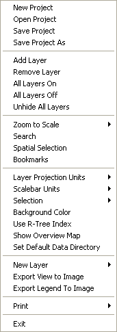
Map
Menu:
-
New
Project: Navigate to the folder where you want to save
the project name. Type in a name and click "Open"
to create the project. Project files for fGIS have a ".ttkgp"
file extension. (This is the same extension used by the TatukGIS®
Viewer and Editor, both of which are also built with the excellent
TatukGIS Developer Kernel. There are many differences between
fGIS and the unique TatukGIS® products. You might, however,
want to look at the
TatukGIS Help PDF for additional insight into some of
the common elements such as Properties and Search functions.)
-
The
project file stores the relative path to any data
layers that are added to the map. This can be useful if
you choose to copy your project to a zip folder or CD,
enabling another user to easily open the project on their
computer if you've included the data files all in one
folder or in the same relative arrangement of folders.
-
The
first georeferenced layer that you add to a project will
establish its base coordinate system (world space). All
the layers added to an fGIS project must be in a common
coordinate system if they are to line up.
-
The
fGIS project file saves the paths to data layers, layer
display properties, the last zoomed view, whether layers
were turned on (visible), and other project parameters.
-
Open
Project: Navigate to an existing project file and double-click
the ttkgp file to open it. The project will resume with the
last saved view. (You might want to associate ttkgp files
with fGIS so you can open them by double-clicking through
the Windows file manager. See Windows® Explorer Help if you
do not know how to associate file types with programs.)
-
Save
Project/Save Project As: Same functions as other Windows
programs.
-
Add/Delete
Layer, All Layers On/Off, Unhide All Layers:
-
Layers
can be added/deleted with these commands, or you can use
the  buttons on the main toolbar.
-
If
you have a lot of layers in a project, the All Layers
Off command can be a shortcut if you want to selectively
turn individual layers back on. On older computers, the
view will redraw more quickly if fewer layers are turned
on.
-
Unhide
All Layers will redisplay loaded layers in the Table of
Contents (Legend). Use the "Hide Layer" command
in the Layer Menu if layer names are taking up too much
space in a legend.
-
Zoom
to Scale sets the screen view. The scale of a printed
map is set through the Print function
on the toolbar.
-
Search
will highlight all of a project's vector objects that contain
attribute data that match the search criteria. Powerful Boolean
search options are available.
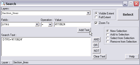
Click
the "Add Text" button to place your search criteria
into the Search Text box. In this simple example, the map will
be zoomed to a Wisconsin Public Land Survey Section located
in Township 11, Range 06E, Section 24 (DTRS code 4110624). The
data files for this example are available in the
State_Park.zip project example.
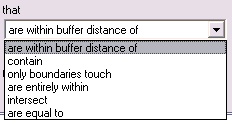
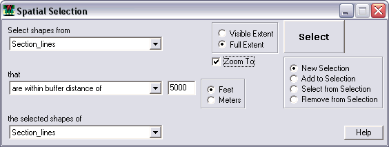
Building
on the previous Search example (above), the following Spatial
Selection would zoom to all Section objects within 5,000 feet
of DTRS 4110624.
-
Bookmarks:
Save views centered on designated X/Y values and zoom level.
-
Layer
Projection Units: The
two options are Meters (UTM, WTM, etc.) and Feet (State Planes,
County Coordinate System, etc.). New projects will default
to Meters. This setting will only affect distance and
area measurements and calculations.
-
Scalebar
Units: The choices are feet or meters, which will affect
the scalebar: e.g.  or
or 
-
Selection:
Options allow a choice for color and transparency of selected
objects. The settings are saved to the project file.
-
Background
Color: The default background is white.
-
R-Tree Index: The
Map > Use R-Tree Index command now saves (and loads) the
Use R-Tree Index setting to the .ttkgp project file when the
user saves the project. The Use R-Tree Index command
(unnecessary for small shapefiles) is now off by default. It
can improve handling of large data layers but may cause a
long pause when the index file is first created.
-
New
Layer: Add a new point/line/polygon vector layer (for
digitizing) here or right-click the work area and select "New
Layer" from the pop-up window.
-
Export
View will save the entire workspace view to a geo-referenced
JPEG, TIFF, BMP or PNG format image (complete with companion
world coordinate files). To save just part of a view to an
image file, use the Export Image Tool in the toolbar.
Choosing
the Export View to Image command opens an options dialog.
By increasing the output image size, multiple images in the
view can be put into a mosaic. Output image size can also
be increased if the view is intended for printing in a publication.
Increasing the output feature size will increase the size
of labels, points, and lines in the output image.
-
WMF
export in Map > Export View to Image dialog will create
a WMF graphics at screen resolution. The vector layers in
WMF images can be resized without loss of quality in drawing
programs. WMF images are not georeferenced.
-
Export
Legend will save the layers list (and any legend symbols
you've enabled in the Properties dialog) to an image file.
Use the legend image in fGIS maps printed with document or
illustration programs.
-
Overview
Map: This displays the Overview Map view. Using the right-mouse-click
popup menu on the Overview Map, a layer can be added and the
extent box color can be changed. The extent box can be used
to change the extent of the main map view by left-clicking
and dragging in the Overview Map view. The contents of the
Overview Map are also saved to the project file. The Overview
Map can also be used in the template files (.tpl) used with
the Map > Print Map command.
-
Set
Default Data Directory: This command will set the first
directory that fGIS look to for data, rather than the fGIS
installation directory.
|
|
|
Layer
Menu:
-
Access
Layer Properties through
this menu or by double-clicking the name of a layer in the
layer list.
-
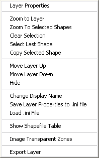
Zoom
to Layer will fit the full extent of the selected layer
to the workspace. The other functions in this section will
zoom to a shape, clear a selection or select the last shape
digitized.
-
Move
Layer: Change the order of layers here or by dragging
a layer's name up or down in the layer list (i.e., legend
or table of contents).
-
Hide
Layer: Useful to save space in the legend (especially
if you have loaded an image catalog with many tiles). The
Map Menu has an "Unhide All Layers" command.
-
Use "Change Display Name" to give layers
a descriptive label (rather than a "path:\file name")
in the legend/layer list. Note: You can also change a display
name by right-clicking a layer name in the map legend (when
not in the Edit mode).
-
"Save
Layer Properties to .ini file" is used to save a
set of display parameters for a layer. A small text file ending
in "ini" is added to the folder where the layer
data resides. If you add the layer in a different project,
the layer will display with the characteristic appearance
defined in the ini file. (If you change the properties of
the layer for a particular project, properties will be read
from the project file rather than the ini file.) If you include
the ini file with data that you send to someone else, they
will be able to open the layer and see it with the display
properties you saved.
-
Load
.ini File: This
command enables layer properties saved to an .ini file to
be used for another layer. Users could create a library of
.ini files and load them as new layers are created.
-
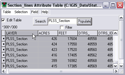
Show
Shapefile Table is a database explorer/editor that shows
the attributes for all the shapefile objects in a layer. Use
it to search for a particular shapefile based on an attribute
value. The tool is also extremely useful for updating or changing
attribute values as elaborated below. The window can be made
full-screen for easy editing of large tables.
-
To
change a field value, check the Edit Table box. Navigate
to the field you want to change, and use the backspace key
to delete a value before typing in a new value. The changes
are immediately saved to the shapefile attribute table.
Area
Fields: Acres or Hectares
Length/Perimeter
Fields: Feet, Miles, or Meters
Point
Coordinate Fields: X or Y
|
If the shapefile attribute
table does not already contain fields with the above
names, but you would like to add the data, then follow
these steps:
1. Select the Layer.
2. Start Editing (right-click the work area and choose
"Start Editing").
3. Click the Attributes Tool (the  in the toolbar).
4. Click on the shape with the Attributes Tool. The
attribute table (data dictionary) opens.
5. Right-click the UID column. Choose "Add Field".
Type in ACRES, HECTARES, FEET, MILES, METERS, or (for
points objects only) X or Y as the field name and
designate the field as a number.
6. Stop editing and save changes.
Next, click "Show Shapefile Table" either
from the Layers menu or by right-clicking the layer
name. Initially, the new ACRES, HECTARES, FEET, MILES,
METERS, X or Y columns are empty. Click Selection/Select
All. Click Table/Update Shapes Measurements
Fields. The new field values will then be filled
in!
|
-
Use
the "Populate" button to change the contents
of Text Fields with whatever text you type into the Search/Populate
text box. In the example above, all the Layer values have
been renamed "PLSS_Section".
-
Using
the Selection > Copy Selection to Clipboard
command on the Shapefile Table dialog will copy the selected
records to the clipboard in tab delimited format. This
format can be pasted into Excel.
-
The
Filter checkbox on the Shapefile Table dialog will filter
the table for the value in the input box for the selected
field. For example, to locate all records with an ACRES
value of 640, type 640 in the Search field, then Search
with Filter enabled.
-
The
filtered records can be highlighted (selected) on the
map with the Selection/Update Selection to Shapefile menu
command. This can be very useful in tandem with the main
menu's Layer/Export Layer command (below).
-
The
number of selected records and the record total are displayed
on the Shapefile Table dialog (not available if Field/Sort
commands are in use).
Additional
information about this tool can be found or by clicking the
Help button in the tool's menu bar.
-
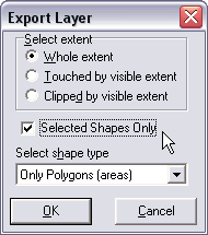
The
"Export Layer" function can clip out a part
of a vector file. The portion saved can be selected by a number
of parameters, including a designated extent or filter based
on a query statement. The exported layer will be saved as
a shapefile. The
Layer > Export Layer command uses the selected layer in
the legend.
|
|
|
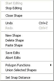
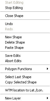
Edit Menu:
-
If accessed from the menu bar, the Edit Menu has the
appearance shown above-left (some choices will be gray and
unavailable, depending on what you are doing). You can also
access the Edit Menu by right-clicking the work area. If you
do, an Edit Menu like the one above-right will appear at your
cursor. Note that the fGIS status bar
turns red when the program is in the edit mode.
-
Start/Stop
Editing: When you start editing, choose the appropriate
digitizer or editing tool from the tool
bar.
-
If
you are digitizing a complex object, but the control point
jumps away from the leading position, undo the last action
to remove the error and then hold down the shift
key before clicking the correct leading position.
Always try to digitize polygons in a counter-clockwise
fashion, so as to give the polygon's vertices a clockwise
winding. This is essential for the Splitter Tool and other
polygon editing functions to work properly. Use
Polygon Functions>Fix Polygon Winding if needed to
give vertices a clockwise winding.
-
You
can modify an object's data attributes table only when
you are in the edit mode. Hit the object with the Attributes
Tool
to open its data table. Right-click the left column to
make changes or add field names. Double-click the right
column to adjust field values.
-
You
must click "Stop Editing" and save your work
before you can switch layers or make property changes
in the legend/layer list.
-
Close
Shape: Sometimes
a polygon shape is left "open-ended" when using
the Edit Points tool OR sometimes the user doesn't want to
double-click a final point when using the New Shape tool. The
Close Shape command closes the polygon shape and enables the
Attributes tool.
-
Undo/Redo:
Same functions as other Windows programs.
-
New
Shape: Selects the digitizer tool and readies fGIS to
create another shapefile object.
-
Delete
Shape: Works only with selected objects in the active
layer.
-
Save
Edits/Abort Edits: Same
functions as other Windows programs.
-
Polygon
Functions: (For details, see the
Polygon Editing Tutorial.)
1.
Subtract Polygon: The geometries of all polygons that
overlap the selected polygon will be subtracted from the selected
polygon. This makes it possible to append polygons to
existing polygons or fill in holes between polygons.
2.
Fix Polygon Winding: Clockwise wound polygons work
best with Split Shape Tool, Append Polygon Tool, and Subtract
Polygon command. Use Fix Polygon Winding to give vertices
the correct order.
4.
Drill Polygon: The geometry of the selected polygon
will be subtracted from the geometry of any polygons that
it overlaps. In this manner you can cookie-cutter-in new polygons.
5.
Delete Part: Individual parts of multi-part polygons
can be deleted.
|
Note:
Subtract Polygon and Drill Polygon commands only
work with shapes that are selected with the Pick
tool.
|
-
Union
Selected Shapes: Merge multiple objects in the active
layer while in the Edit mode. Use the Pick Tool  and Ctrl key to select multiple objects. This command works
for lines and polygons.
and Ctrl key to select multiple objects. This command works
for lines and polygons.
-
Select
Last Shape: Useful for selecting a shapefile just created,
either to drill, subtract (polygons) or delete the object.
-
Copy
or Paste Selected Shape:
Shapes can be copied from other layers to the
layer being edited. Line objects can only be pasted into line
layers, polygon objects into area layers, etc. The shape is
copied in WKT (Well-Known Text) format so that users could
create or edit a shape in a text editor and paste it directly
into the layer. To see the format, copy the shape and paste
into a text editor.
-
Set
Snap Distance: The system default distance is 15
pixels. Values greater than 35 are not recommended. (Select
the layer to snap to on the fGIS toolbar.)
-
WTM
Location to Lat/Lon: Copies the lat/lon of the position
clicked to the Windows clipboard. This tool works only with
Wisconsin Transverse Mercator data sets.
|
|
|
Utility
Menu:
-
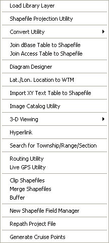
"Load
Library Layer" simplifies selecting GIS layers. If
you have a large collection of enterprise GIS data,
the naming conventions often result in cryptic files names.
What's more, the layers might be stored in many folders (which
also have code names). You can solve the problem of remembering
what's where by creating a DBF file with a common alias for
each layer and a path to each file. Once you create such a
table, just use Load Library Layer and click a shape layer
in the table. fGIS will add the layer to your map's table
of contents.
Here's
an example of a DBF file containing paths and plain language
file names:
You
can use Load Library Layer/Add Env Variable to set a path to
each folder, or you can use Notepad to do the same by creating
a file named "env.txt" in your fGIS program folder.
Here's a sample environment text file for the first two folders
shown above:
In
this example, the shapefiles can be found on the user's E:\
drive in the path as shown. Once the Library Layer file is set
up, just click once on the layer you want, and fGIS will load
it.
Users
can also to select a different env.txt file instead of the one
in the /fgis directory by using the Env > Set Env File command
on the Load Library Layer dialog. The default env.txt file can
also be set in the language.ini file.
The Load Library Layer dialog can optionally load an .ini file
specified in the INI_FILE field of the Layer Table. This field
can use environment variables for the path.
When
a new Env file is selected with the Env > Set Env File command
and the project is saved, the new Env file name will be saved
to a file named fgis.ini and used as the default Env file.
In the Load Library Layer dialog, layer display names can be
specified in a field named "Alias" in the layer table,
however the names stored in a .ini file will take precedence.
|
WISCONSIN
FORESTERS NOTE: The fGIS distribution zip archive
includes an "env.txt" file and a "layrdata.dbf"
file, which are based on the layout of the Wisconsin
DNR dvgislib data store. The env.txt file assumes
that your Wisconsin DNR GIS data is on your local
computer in the following path: "C:\GIS_DATA\dvgislib\wi_tile\".
If your data is in a different path (such as a Regional
tile), you can edit the env.txt file (use search and
replace in Word) to reflect the path you use. Do
not use spaces or the dash (-) character in folder
or file names! If you open layrdata.dbf with Load
Library Layer/File/Open command and the shapefile
is present, then it will load in fGIS when you click
its row in the data table.
Keep
in mind that the Wisconsin Regional library tiles
do not contain all the layers present in the full
Wisconsin tile library directory. If a layer is not
present on your local drive, you will get the following
message:
|
-
The
Shapefile Projection Utility converts shapefiles between
Geographic (lat/lon), UTM NAD83 and WTM NAD83 coordinate systems.
In the following example, a Geographic Census TIGER shapefile
is converted to a UTM Zone 15 file:
Be
sure to organize your shapefiles into folders with logical names.
If a source file has a coded name, you might want to change
it to plain language as shown in the Output Shapefile above.
(Avoid the use of "-" or other non-standard characters
in file names and directory names.)
Wisconsin UTM zones numbers are
here. Worldwide
UTM zones are included in the fGIS Shapefile Projection
Utility.
-
The Convert Utility interprets
unit measurements, translating a value from one unit to any
other. Selecting the Convert Utility starts Josh Madison's
Convert program (more information about Convert can be found
in the convert_readme.txt file in the fGIS system folder).
Exit the Edit mode before using Convert.
Typically,
you'll use convert by (1.) copying a value from an attribute
table (click a cell to make it active, then right-click the
value and copy). In Convert, (2.) drop the value to be translated
into the Input box and read the converted value in the Output
box. Use the tabs in Convert to choose the input and output
units. The two steps are shown below using a square meter area
value from a Wisconsin DNR PLSS section attribute table, changing
it to acres.
-
The
Join dBase Table to Shapefile Utility can join a dBase
table to a shapefile's attribute table based upon a common
field from each. The common field names do not need to be
identical. The common fields should, however, contain the
same type of data.
The
join is performed in a one-to-one relationship manner only.
Only the first record from the input dBase table in a one-to-many
relationship will be joined in the output shapefile.
The
join process may take several minutes for very large shapefiles
and dBase tables.
Note:
Microsoft® Excel tables can be easily exported as dBase files
for use in fGIS.
-
Join Access Table to Shapefile: The
Join is a "live" join to the database. The
joined fields are visible in the Layer Properties, Attributes
Tool, and Search dialogs.
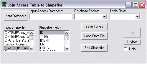
The
Sort Shapefile function can improve the quality of an Access
table join:
-
This
function will sort the selected shapefile by the selected
attribute field and output it to a new shapefile. The
new, sorted shapefile should be added to the theme (legend
or table of contents) in order to take advantage of it for
the Access table join in (b).
-
Access
table records are now sorted by the join field prior to creating
the join. The join works best if there is a one-to-one
relationship between the records in the shapefile and the
Access table, AND if the records in each dataset are sorted
by the same field.
An
Access table join (created via the Utilities > Join Access
Table to Shapefile dialog) can be saved to and reloaded from
the project file.
-
Diagram
Designer: Diagram Designer is the print layout module/technical
illustration program. Access it either through the Utility
Menu or through the prompt when using the Export Image Tool.
Detailed instructions about
using Diagram Designer are here.
-
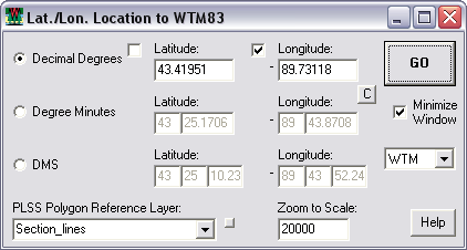
Lat./Lon.
Location to WTM:
The Lat/Lon Location to WTM utility is a "Go To"
utility that works with WTM, UTM or WGS84 data. If requisite
shapefile layers are loaded, it can also serve as a Public
Land Survey System locator.
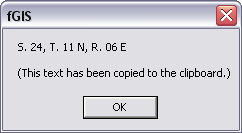
This
Public Land Survey System section finder is specific to users
with data that contain a DTRS* or DTRSQQ attribute field.
Type in the lat/lon of a location and click GO to zoom to
that PLSS section. A large red dot is placed at the designated
coordinates. The layer containing the DTRS reference data
must be specified. The Section, Town and Range information
for the lat/lon coordinates are copied to the Windows clipboard.
This
tool works with either UTM zones or WTM (Wisconsin Transverse
Mercator) data. UTM users can modify the language.ini
to display "UTM" text instead of WTM and place their
UTM zone at the top of the projection list. For
example, if your data is in UTM zone 16, add the following
line to the [frmLatLongToWTM] section of the language.ini:
frmLatLongToWTM.lbxProjections.Items[0]=UTM,16
The
dialog checkboxes by Latitude and Longitude add "-"
signs to the input coordinates to designate locations in the
southern or western hemispheres.
The WTM location to Lat./Lon. command (from the view's right-mouse-click
popup menu) will also utilize whatever projection is selected
in the Lat./Lon. to WTM form (WTM or any UTM zone). Again,
UTM users can modify the language.ini to display "UTM"
text instead of WTM, or to place their UTM zone at the top
of the projection list.
*The
DTRS code is a seven-digit number that uniquely identifies
all PLSS sections in Wisconsin. A 2 in the first digit indicates
a range direction of West. A 4 in the first digit indicates
a range direction of East. The second and third digits contain
the township number (0 through 53). The fourth and fifth digits
contain the range number (01 through 20 West, 01 through 30
East). Digits six and seven contain the section number (01
through 36). See the "Section_lines" shape (actually
a polygon layer) in the State_Park.zip example.
-
Import XY Text Table to Shapefile: This command will
create a point shapefile from a comma delimited or tab delimited
text table with XY coordinates in decimal degree format.
The
text file should be laid out in the following order: ID, X (longitude),
Y (latitude), Text. The first row of the table should contain
field names (which can be substituted for the "ID, X, Y,
Text" variables). Text containing spaces should be enclosed
in double-quotes. See an example
text file here.
Click
"Import" to create the point shapefile.
The Import
XY Table to Shapefile dialog adds the new shapefile to the view
after creating it.
Additional
data values can be added to the new shapefile's attributes with
the Join DBF or Join Access Table Tools above.
|
Hint:
If you use a simple program like
Waypoint+ to download waypoints from a Garmin
GPS receiver and save them as comma-delimited text,
the "Import XY Text Table to Shapefile"
utility in fGIS can create a GPS waypoints shapefile
layer. You may need to project the
GPS lat/lon coordinate shapefile to UTM or WTM
to align with your other layers.
|
|
| |
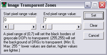
-
The Image Catalog Utility dialog (Utilities > Image
Catalog Utility) will load all layers in an image catalog
and optionally hide them all upon loading. The DNR uses
image catalogs to load groups of DRGs. There are also commands
to Turn On/Off & Hide/Unhide all image layers as a group.
-
See
instructions for the 3D Viewing Utilities here.
-
Hyperlink Utility: This
tool changes the function of the Pick tool to display the
file specified by the filename in the Hyperlink field for
the shape selected. Images, text documents, web pages, etc.
can be used.
-
Search
for Township/Range/Section: This tool requires that an
appropriate Public Land Survey System layer with a DTRS attribute
is loaded.
-
Utilities > Routing Utility:
The Routing Utility will locate addresses (using the From
text and the Find Address button) and find the best route
between two addresses (using the Find Route button) in the
Routing Layer. The Routing Layer is typically a Road shapefile
based upon the US TIGER roads data. Such a layer is available
in the State_Park.zip fGIS sample dataset and for WI from
the DNR. See dialog for more help. (Attribute names shown
in light gray text in the dialog window, set for US TIGER
Census road layers, may also be edited.)
-
Utilities > Live GPS Utility [BETA]:
This utility will display the GPS location for a GPS receiver
outputting NMEA format data connected to the COM port. The
location can optionally be snapped to a line layer to correct
for moving features. This utility has not been tested with
moving GPS receivers. See the dialog for more help.
-
Utilities > Clip Shapefiles: Use this dialog to
clip line or polygon layers to the boundaries of a polygon
layer. Point
layers can NOT be clipped using this dialog. To clip out point
layers, select the points using the Map > Spatial Selection
dialog, then create a new shapefile of the selected points
using the Layer > Export Layer dialog.
-
Utilities > Merge Shapefiles:
This dialog can be used to merge multiple shapefiles into
a new one. All fields from all input layers will be included
in the output shapefile.
-
Utilities > Buffer: Select a point,
line or area object and create an area shapefile file around
it at a designated radius or width. The following example
creates a one-mile circular buffer around the point "WRPQ-AM":
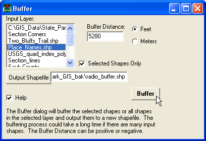
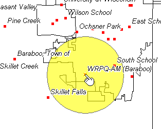
The
Buffer utility can also be used to create buffers around multiple
selected objects or all the objects in a layer. The buffered
area will initially be displayed with solid gray fill, which
can be changed through the Properties dialog.
-
New Shapefile Field Manager dialog
to retrieve default attribute table settings. These settings
are stored in a file named fgis.ini that is stored in the
same directory as fGIS.exe. The New Shapefile Field Manager
dialog can also be accessed from the Utilities > New
Shapefile Field Manager command. An example fGIS.ini file
to be used with the New Shapefile Field Manager is included
(open it in Notepad or other text editor).
-
Utilities > Repath Project File:
This dialog is useful for modifying a project file after data,
projects, or directories have been moved.
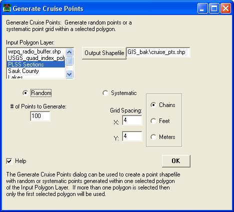
-
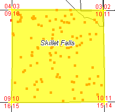
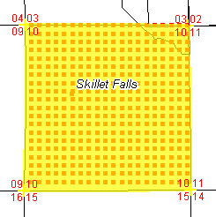
Utilities > Generate Cruise Points:
Select an area object and fill it with either random or systematic
points. The generated points are saved as a shapefile, which
can be used in fGIS or transferred to a GPS unit for navigation.
Other GPS software such as DNR Garmin Tool or OziExplorer
would be needed to upload the points to a GPS receiver.
|
|
|
|
|
|
Random
Grid Points
|
Systematic
Grid Points
|
|
|
|
Help
Menu:
|
|
|
|
|
